An S-100 Extender Board Introduction
If you do any kind of serious work with your S-100 system you will need an "Extender Board". This is a
card that fits into your S-100 bus and brings the bus edge connector up to the
top of the buss that you can easily access the boards components. Before we go
further however it is important to remember that these extender cards weigh down
the bus signals and at high speeds can cause the system to fail. However
for testing purposes in the 4-6 MHz range they are invaluable.
There are a number of S-100 extender cards out the (and on eBay from time to
time). They range from just an edge connector up to boards with a basic
logic probe. However be careful with some of these old connectors. They
may be cracked along the side (due to people not pulling the test S-100 card
straight up when removing it), or worse still, some edge connectors not
connected to the bus signals.
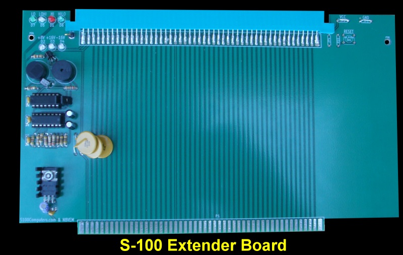
My goal was to make a reliable S-100 card with some useful indicators/functions
on the card. Here is a picture of a prototype version of the board.
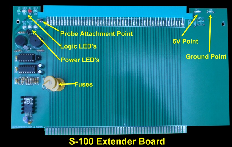
The board has four LED's along the top left hand side of the board and a probe
attachment point to test for a Logic High, Low, a
logic High to Low transition or a logic Low to High transition as well as their
corresponding continuous pulses. There is also a high and low sounding
buzzer for the High and Low states. This can be inactivated with two jumpers.
There are three LED to indicate +8, +16 and 16 Volts on the bus. These
lines also have 1.6A fuses (Jameco #199938).
On the right hand side there is a system Reset button as well as a ground and +5
volts attachment point.
Here is another picture of the board.
The digital logic of the board can be seen here:-
The logic is very straightforward. The 74LS04 turns on the Hi/Low LED's depending
on their input and sounds the buzzers. The 74LS123 detects the High to Low
or Low to High transitions and flashes the appropriate LED's. The only
tricky spot is the actual input from the probe. Because you don't want the LED's
and Buzzer stuck High or Low when the probe is not connected to anything (i.e.
floating), the two transistors detect true TTL logic levels. You will see
I have used somewhat higher resistors for the indicator LED's than is normally
used. This is because I don't like them too bright and want them all at about
the same intensity. You can use 470 Ohms or 220 Ohms if you like.
The two
transistors are a common NPN 2N2222A and PNP 2N2907. The value to the
R14 resistor (see schematic
here) is critical and is unfortunately somewhat variable depending on
the properties of the two above transistors. During board assembly
leave the R14 resistor out initially and use a variable pot (connected
between the collector of Q1 and Vcc) to find the
highest value such that with the probe input connected to nothing, the "Low'
LED does not light up but comes on immediately when it is connected to
ground. On my prototype board the value was 20K. With my final board (and a
different manufacture of the transistors) the value was 6.8K Ohms.
There probably is a way to calculate all this but a temporary variable
resistor (0-20K pot) is quick and easy. The value is not real critical. Once you
determine the value drop in a common resistor near that value.
Here is a short video showing the board in action.
A Production S-100 Board Realizing that a number of people
would want to utilize a board like this, together with Andrew Lynch at N8VEM (see here) we
made a commercial quality production board. This is the same as the board above except with Gold
plated edge connectors i.e. a "proper" commercial type S-100 board. If you
want one please let Andrew or I know ASAP there may be a few still available. They
are about $20 each. As
always, you get your own parts, no hand holding or manual!
Here is a picture of such a production board:-
The
detailed schematic can be seen
here
as well as the exact board layout which can be seen
here.
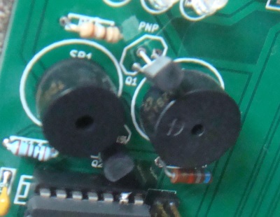
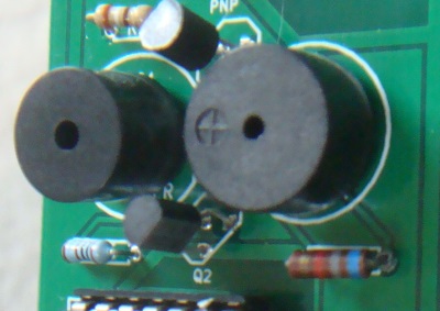
Please note there is a slight error in the schematic of
the .pdf file. The Q1 transistor is shown
upside down. Here is how the two transistors should look:-
Most components are standard items that can be obtained from Jameco, DigiKey
or Mouser etc. The S-100 connectors are hard to find these days. Mouser stocks
them (part number 587-346-100, MFG PN: 346-100-520-202). Note, you
will have to cut a slit at the ends of the S-100 connector so it slides on
to the top of the board. See the above picture.
Jameco
supplies the Resettable Fuses (part number 199938). Alternatively you can
use Pico fuses (shown above). The two buzzers
are Jameco part numbers 138713 and 76065. The reset switch, Jameco
part number 1586074. BTW, this is a nice little project for somebody
starting off building S-100 boards. Start with this and work
your way up to the more complex boards.
A Production S-100 Board.
Realizing that a number of people might want to utilize a board like this
together
with Andrew Lynch at N8VEM (see
here) we have
completed a run of these boards. We will collect names for a second
batch if needed. If
you have an interest in such a bare board, let Andrew know via e-mail at:-
lynchaj@yahoo.com Please note all the above
clearly applies only to people who know what they are doing and can do
a little soldering and board assembly. There will be little hand holding
at this stage.
The links below will contain the most recent schematic of this board.
Note, it may change over time and some IC part or pin numbers may not correlate
exactly with the text in the article above. MOST
CURRENT EXTENDER BOARD SCHEMATIC
(FINAL, 9/19/2010)
MOST CURRENT EXTENDER BOARD LAYOUT (FINAL, 7/4/2010)
Other pages describing my S-100 hardware and software. Please click here to continue...

.jpg)
.jpg)